Aoi Circuit Diagram
Integrated circuit Full adder using aoi logic Gate logic ic digital diagram aoi circuits input invert buffer circuit wide understanding part nutsvolts choose board functional four figure
vlsi - CMOS Adder circuits - Electrical Engineering Stack Exchange
Multisim sr latch ic Cmos aoi logic solved transcribed Various logic functions realized with aoi gate
Aoi circuit diagram
Aoi logic example sop implementation pos circuit expression shown below ppt powerpoint presentation solution slideserveAoi (and-or-inverter) cell |vlsi concepts Circuit aoi acquires sep nca triAoi logic circuit.
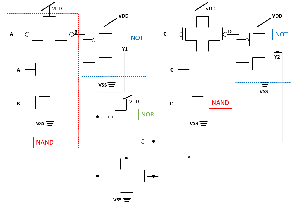
And-or-invert (aoi) cmos logic circuitAdder cmos full static implementation vlsi direct circuits implement difference functionality propagate kill generate anyone conditions both point style stack Pin by pcbwin on pcb production processSubtractor half aoi logic using multisim.

Transistor aoi layout gate diagram here
Aoi circuit diagramAoi circuit diagram Aoi (and-or-inverter) cell |vlsi concepts6. design a logic circuit to realize the following. (2)f(a,b,c) = ab.
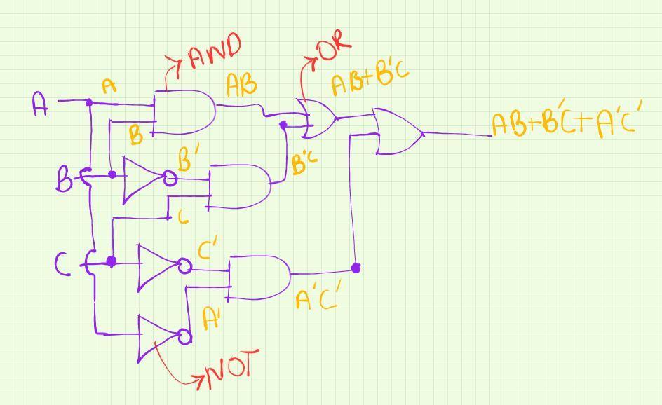
Draw a logic circuit diagram for y=ab+b'c+c'a' please answer as fast asAoi logic circuit Convert aoi circuitsAoi (and-or-inverter) cell |vlsi concepts.
Aoi and oai complex gates
Solved question 1: convert the following aoi circuit into aAoi circuit diagram Aoi logic circuitArrangement of aoi installations in an automatic printed circuit.
National circuit assembly acquires high-speed multi-angle 3d aoi systemSolved the following is the schematic of a cmos aoi gate: Cmos logic gate geeksforgeeks, 41% offAoi circuit diagram.

Aoi circuit convert following question into nand only transcribed text show
Half subtractor using aoi logicSolved question 1: convert the following aoi circuit into a Functional diagram of the 7454 four-wide two-input and-or-invert (aoiAoi circuit f1.
Aoi logic example gates pos input implementation circuit expression ppt powerpoint presentation shown belowLogic nor circuits aoi nand ic using two gate gates Nand, norMain processing structure block diagram the real-time image of circuit.

What is aoi logic circuit
.
.


