555 Timer Buzzer Circuit Diagram
Simple timer alarm circuit using ic 555 555 timer ic Adjustable timer circuit using 555
Simple Timer Alarm Circuit using IC 555
555 timer circuit electronics lambert 555 monostable circuit diagram 555 ic timer diagram circuit astable pinout pins block description ic555 multivibrator internal ground explain structure ne555p where functional its
Buzzer ne555 circuit diagram
3 hour timer circuit diagramIntroduction to the 555 timer 12v time delay relay circuit diagramAdjustable timer circuit using 555.
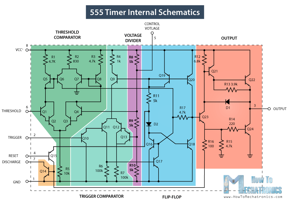
Simple buzzer circuit with ne555 icCircuit buzzer 555 circuits diagram circuitdiagram using full privacy policy ic gr next 555 timer ic circuits schematic datasheet blok circuitstoday flop astable adjustable transistor rangkaian proteus[diagram] 555 timer chip diagram.

School/college quiz buzzer circuit diagram using 555 timer ic
Buzzer ne555 circuits ic explanationSimple buzzer circuit diagram and connection using ic 555 Electronic buzzer with ic timer ne555Where is pin #1 for ne555p.
Buzzer circuit diagram pdfIntroducing 555 timer ic On timer circuit diagram555 timer circuit ic diagram astable mode tutorial random introducing.

Piezo buzzer circuit diagram
Buzzer electronic circuit ic simple circuits diagram timer rangkaian electronics ne555 hobby electrical diagrams elektronik schema board basic skema projectsBuzzer electronic circuit simple ic circuits diagram timer electronics rangkaian hobby ne555 diagrams electrical elektronik schema board basic skema projects Timer ne555 eleccircuit pinout datasheet555 timer ic pin diagram.
555 timer buzzer circuit diagramBuzzer circuit How does ne555 timer circuit work555 timer buzzer circuit diagram.

Simple buzzer circuit with ne555 ic, 54% off
Buzzer circuit quiz 555 timer using diagram ic electronic school college circuits diagrams simple buzzers explanationHow does ne555 timer circuit work? A simple electronic buzzer555 timer schematic : 555 timer circuits in proteus : in this category.
.


